


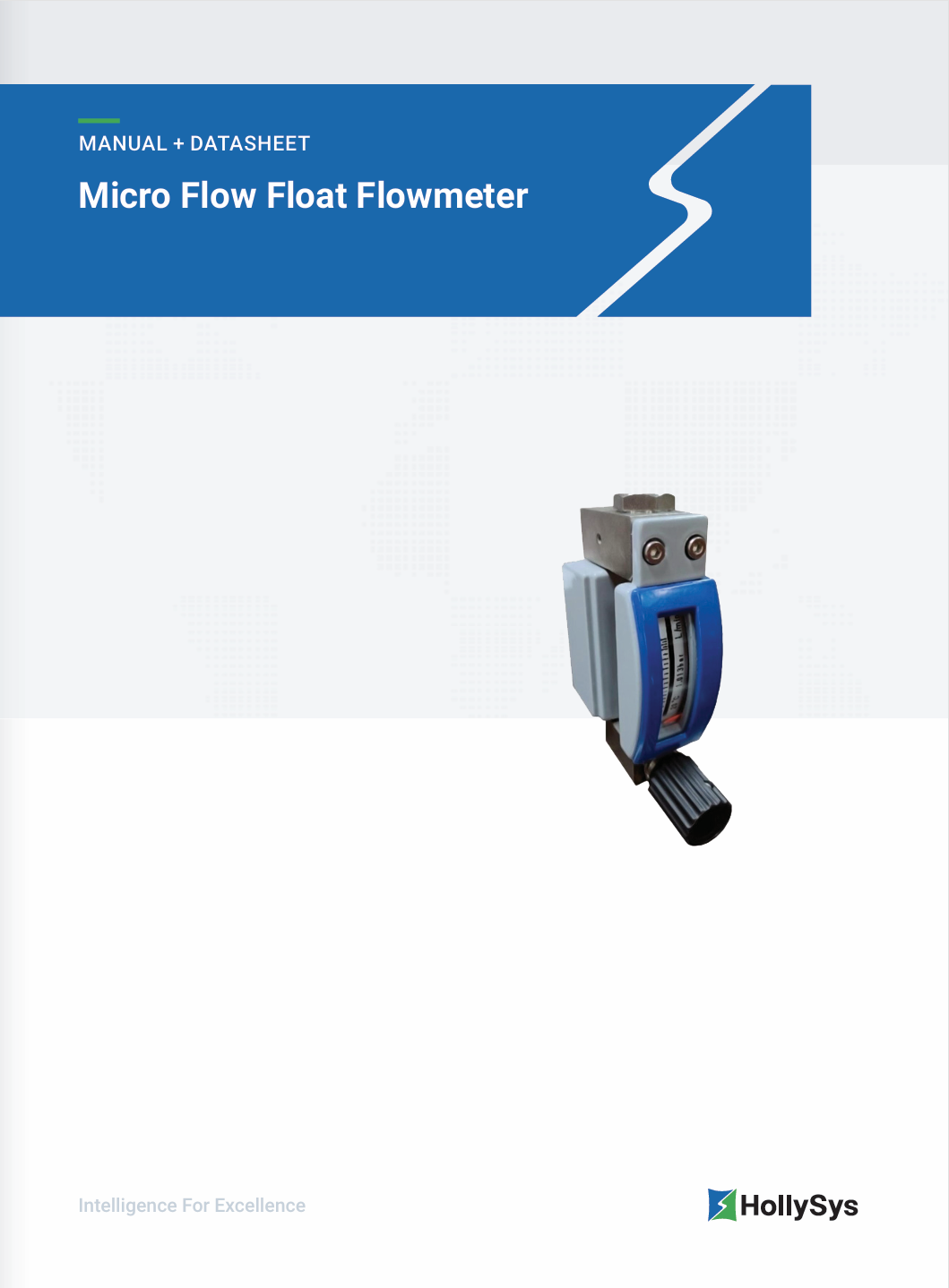
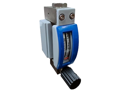
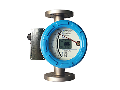
HT57 Micro Flow Float Flowmeter
About HT57 Micro Flow Float Flowmeter
HollySys micro flow float flowmeter is designed based on the principle of magnetic coupling, suitable for measuring small-volume flow rates of liquids and gases. Each flow rate of the measured medium corresponds to a fixed position of the magnetic float inside the measuring tube. This position is indicated by a pointer in the indicator through magnetic coupling, and the volume flow rate of the liquid or gas passing through the measuring tube can be obtained by reading the scale on the dial. In addition to being equipped with an on-site indicator, the micro flow float flowmeter can accommodate up to two switch signal outputs for flow over-limit control. The remote indicator features an LCD that displays the instantaneous flow rate of the mea sured medium and supports 4-20mA two-wire current output and HART® protocol digital communication. The micro flow float flowmeter can also be equipped with a flow control valve at its inlet or outlet, integrating the flow control valve with the flowmeter for convenient adjustment of small flow rates. In applications with significant medium pressure fluctua tions, a constant flow valve can be installed at the inlet or outlet to ensure stable and accurate measurements. Thanks to its compact size, lightweight design, stable and reliable operation, minimal maintenance requirements, low straight pipe section requirements, and diverse installation options, the micro flow float flowmeter is widely used in industries such as petroleum, chemical, and steel for small-flow measurement and process control.


Product Features
-
 Ultra-Low Full Scale Range
For water (20°C): Full scale as low as 3 L/h
For air (20°C, 0.1013 MPa): Full scale as low as 50 NL/h
-
 Compact and Lightweight with Diverse Connection Options
The flowmeter offers process connections such as threaded or flanged options, allowing horizontal or vertical installation based on the on-site piping system
-
 Supports Two Switch Signal Outputs
One adjustable bistable reed switch outside the indicator
One or two NAMUR switches inside the indicator for convenient on-site flow monitoring
-
 Constant Flow Valve for Pressure Fluctuations
In applications with frequent medium pressure fluctuations at the flowmeter inlet or outlet, a constant flow valve (PE or PA type) can be installed. These valves ensure stable flow output even when the inlet or outlet pressures vary.
-
 Optional Flow Control Valve
A needle valve can be installed at the inlet or outlet of the flowmeter, enabling precise and convenient micro-flow adjustments
Technical Parameters
-
Measuring medium
Liquid and gas
-
Flowmeter model
G22 horizontal connection, G24 vertical connection
-
Measuring range (100% full scale)
Water (20°C): 3 to 100 L/h; Air (20°C, 0.1013 MPa): 50 to 3400 L/h
-
Range ratio
10:1
-
Measurement accuracy
± 4% F.S. Special ± 2.5% F.S
-
Medium temperature range
-25°C to +120°C for field indicators, -20°C to +70°C for remote indicators, maximum tempera ture ≤ 200°C
-
Maximum medium pressure
≤ 13 MPa
-
Ambient temperature
-25°C to +70°C
-
Switch signal output
Bistable reed switch signal; 2-Wire NAMUR limit switch SJ2-S1N
-
Electrical remote signal output
2-Wire 4 to 20 mA output superimposed HART Protocol Digital Communications
Related Products
-

 AFM2000 Metal Tube Rotameter
 -
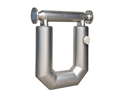 P Series Coriolis Mass Flow & Density Meter
 -
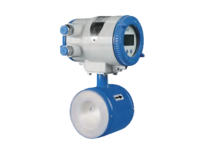
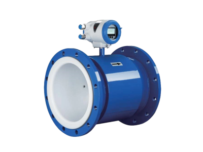 AF-EMF89 Intelligent Electromagnetic Flowmeter
 -
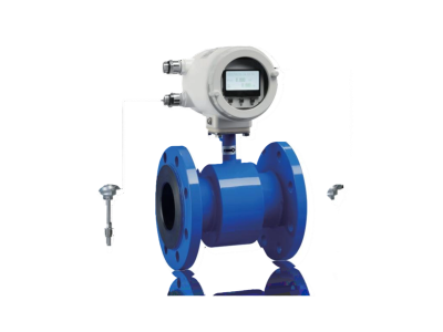
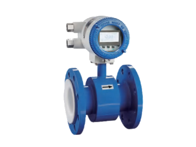 AF-EMF8D Electromagnetic Flowmeter for Low Conductivity
 -
 AF-EMF8J Electromagnetic Flowmeter for Slurry & Pulp
 -
 AF-EMF8W Electromagnetic Flowmeter for Low Flow Measurement
 -
 AF-EMF8E Electromagnetic Energy Meter
 -
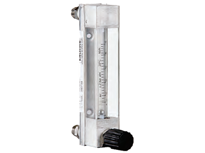 DK800 Glass Tube Float Flowmeter
Services & Support


The Latest


-


HollySys Showcases Advanced Rail Solutions at LTA Technology Sharing Workshop
 2026-06-18
 -

HollySys Supports Strategic Refinery Upgrade Project for Pemex, a Leading Latin American Energy Major
2026-05-28 -

HollySys Enables SIL3-Level Safety at BASF Zhanjiang Verbund Site Aligned with the World's Highest Safety Standards
2026-04-17